Single Ended headphone amplifier with 5842 triode (4)
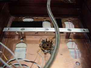 |
The aluminum rail at which the elco's are to be mounted. You can see the input wiring here, this is done because it was my second attempt to determine a layout without picking up hum from the powertransformer... |
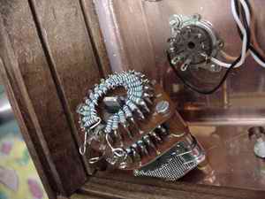 |
The series stepped attenuator is mounted. Look here to see how it is made.. Filament wiring is placed. I use teflon insulated stranded wire for this purpose. |
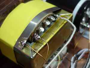 |
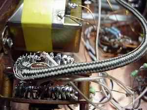
THe shielded outputtransformers. Connect the shield to ground. As you can see, the shield is placed around the transformer; never place the shield surrounding the windings only, this will create a short circuit! |
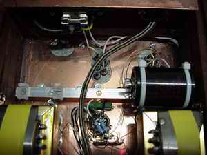 |
One elco mounted. Use nylon saddles to attach the tie-raps to. This makes it easy to replace the elco's later on. If you have the chassis mount clamps to go with the capacitors, screw them to the wood and place the elco's in them. This spears you making the aluminum rail. |
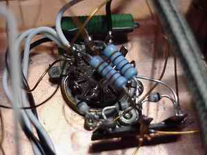 |
The rectifier's tube socket. You can see the Graetz bridge of BYV26E's. The middle of the 3 lug solder terminal is connected to chassis. One of the not connected socketterminals is used to connect the resistor used for decreasing the filament voltage. The blue resistors are the balancing resistors for the filament. |
 |
Connection of the series stepped attenuator. I use antique paper/paper/cotton insulated wire, copper solid core, 0.4mm for signal. The power supply wiring is 1.4mm magnet wire. |
_______________