A phono preamplifier with LCR RIAA correctionfilter
Introduction.
As probably known there are multiple ways to deal with the (mechanical) correction put to music signals as being cut
on records. It is simply not practical (even possible) to cut the full audio spectrum onto a record without correction.
Higher frequencies are boosted where the lower frequencies are attenuated. This is logical as you look at the sinuses
representing the music and imagine how the stylus would have to move following it: the smaller the intervals the higher the
frequency, the longer the intervals the lower the frequency. Dynamic range can be seen in the height of the sinuses, a higher sinus
represents louder music and vice verse. First one we call frequency modulation, the latter amplitude modulation.
Most determining however are physics. The constant velocity character of (cutting) styluses results in decreasing height
in sinuses at higher frequencies and an increasing height of sinuses at lower frequencies.
On top of that we have the left and right channel containing different aspects of the musical signal which forms the stereo effect.
Where the music itself is read by the stylus in a horizontal movement, the stereo information is read vertical movement. This is why mono
cartridges can not playback in stereo. To be able to cut all this into a record within the audio spectrum and with acceptable
minutes of music per record side, correction must be used. In the early days most of the big record companies used their own
correction, it was only later in time when the music industry standardised this into the RIAA-correction. All about marketing.
The RIAA-correction focusses on two poles: 2122hz and 500hz. A third one may be used to fight rumble, 50hz.
So if we want to reproduce music cut onto records, we need an amplifier with an ability to inversely re-correct the musical signal. Most of
the times this is done using a combination of resistors and capacitors which form filters for the two poles. These filters can be used actively or
passively. Actively as in a feedback loops and passively as in between amplifying stages. I really like actively but incorporated
into the load of a pentode as the load determines the amplification factor of a pentode.
Sometimes coils are incorporated into filters as well, in some cases, tweaked into the
absense of capacitors. Hat off!
No matter what solution is used, there will always be an attenuation of 20dB when a RIAA-correction filter is used.
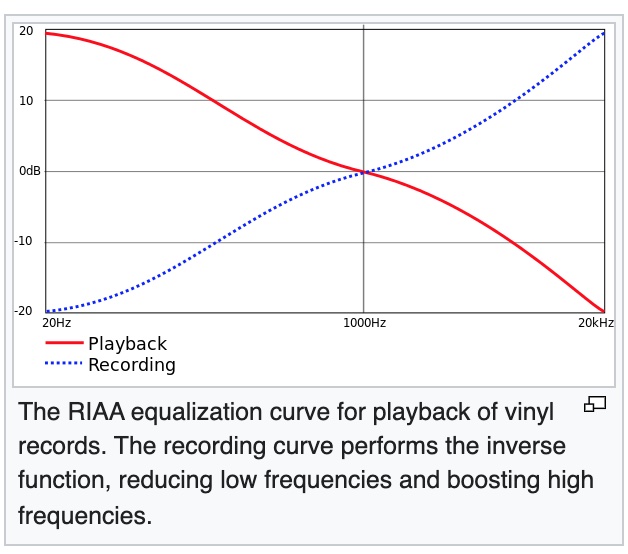
Image taken from Wikipedia
LCR RIAA-filter
So what is a LCR? L stands for inductor, C stands for capacitor and R stands for resistor. So in essence a coil is added to the filter.
I do like coils! But why adding a coil to a filter? It will make it more complex and we do like simple. The advantage of a
LCR-filter is that it remains correct despite the wearing of tubes. Wearing of tubes means that they go off-specification. And those
specifications are part of the filter equations when using RC-filters. Also there are no high value resistors used in a LCR filter, all
values are relatively low compared to standard RC filter resistor values. This means that the filter itself is less prone to pick up spray
fields and RFI. Alike passive RC filters, the LCR is less susceptible to power supply ripple. Disadvantage is that the LCR filter needs to be driven by a
low impedance stage where 600Ohms seems the standard. Also the coils need to have a frequency independent inductance, so high quality
design. And when we read high quality we know that prices will be high. Yes, a LCR filter is ridiculously more expensive than a RC filter.
Will it be worth that extra investment?
Hashimoto H-EQL.
When possible I do buy local, so one of my first stops is always Acoustic Dimension to
have a look what is available there. I remembered LCR units by Allnic but those were not available anymore. Hashimoto H-EQL however was
available and even in stock. So a visit later I had them on my shelve. Same midday, no faster delivery than that!
Looking at the included application note and diagram, I was wondering what all those Japanese lettering would read, luckily an electronic
diagram is like Latin in the medical world.
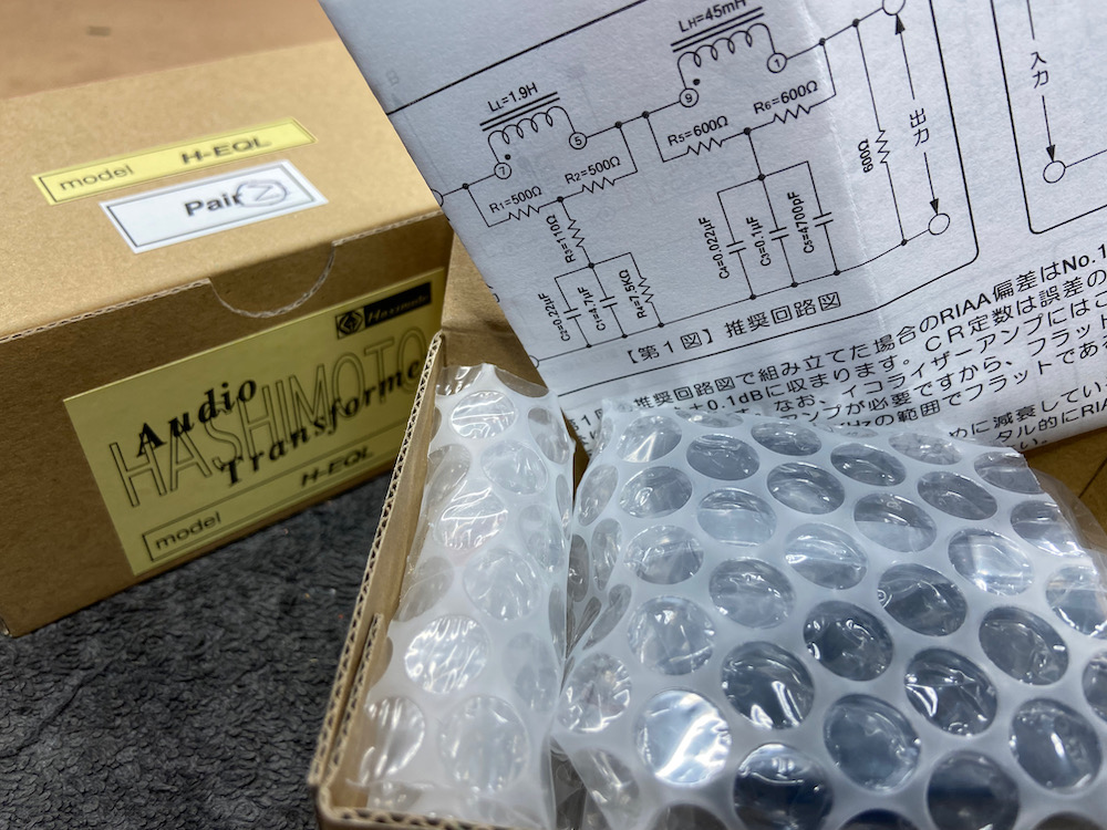
Hashimoto H-EQL with diagram.
Dry run testing the LCR!
Curious about this approach on RIAA correction, I took the RIAA filter component out of the load of my CF50 phono amplifier and hooked the
LCR filter at the output. Output of that phono amplifier is low impedance thus suited and the filter will "look" into an
line input transformer at the preamplifier. This way A and B comparison is not possible, but listening first on the active RIAA correction,
modding the amplifier and hooking up the LCR filter, took just 10 minutes. For this occasion the capacitors were Wima MKP and 1% metalfilm
resistors, all as part of the interlink to the preamp.
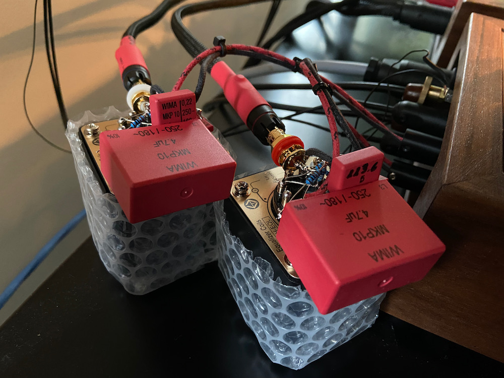
Dry running the LCR filter.
The difference was surprisingly big. No need to switch back. Sound was more dense and laid back without loss in detail. Tone remained (I
need tone, lots of it) and energy was added in the lower regions. Different, not way better, different. Question if it suits the taste
better and it does. This justifies a separate design!
The design.
A two chassis solution is the preferred way to a dead silent phono preamplifier, so signal an power supply apart.
As said I do like coils and have a preference in transformer coupling. To my ears the right transformer adds energy to what a coupling
capacitor will do as well. So no disqualification on coupling capacitors, just my preference. This means that the amplifier will be transformer
coupled which can also serve the LCR's low impedance requirement. Design will be: SUT - transformer loaded first stage - LCR filter - transformer
loaded second and last stage.
Two SUT's are used: one for the Dava Reference and one for the Koetsu Tiger Eye. Both on separate inputs tweaked by a resistor on the
secondary. The Dava will be served by a Dava SUT (Neuman design 1:25), especially made for Dava cartridges. The Koetsu will be served by a custom
made Tribute SUT (Toroid 1:15).
First stage is a triode connected D3A. High transconductance, high amplification factor thus low internal resistance. Ideal for transformer
loading. The Tamura A4714 is an excellent choice, it represents a 5K primary and two 150Ohms secondary together with a 6Ohm tap as well. The
150Ohm taps in series make 600Ohms, perfect to drive the Hashimoto H-EQL. The 6Ohm tap is not connected. In this configuration the step down
ratio of the A4714 will be 2.8:1. So we will loose some gain out of the 77 what the D3A can deliver. The D3A is biased at 15mA as part of the
power supply design which will be addressed later on.
The LCR filter will be completed by the capacitors and resistors as supposed in the H-EQL datasheet. Key for a good re-correction of the RIAA
curve are precise value components. Especially for measurements, maybe not so for musical experience.. So in with 1% values metalfilm
resistors and specially selected capacitors. The capacitors are both old stock, Western Electric (Yes, #MeToo) and Vitamin-Q together with
Russian K40 types. Coincidentally (really?) I had one WE capacitor with the just about the exact value needed and my friend
supplied me with the second one. So two values combined into one. And this type WE was designed for signal applications at that time. Maybe nice to know
is that WE has designed many types of capacitors, all with a distinctive purpose. If that purpose matches the application, sound will be very
special. If not, sound might not be special at all. You might want to take this into account, not only for sourcing the right type yourself, but as well
when commenting on them online..
This can be no coincidence..
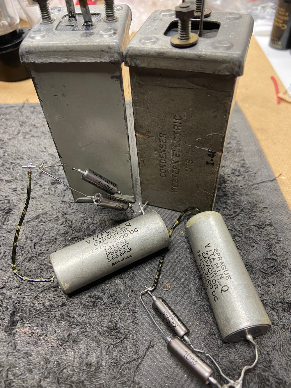
Together with the selected Vitamin-Q and K40..
The second stage is an EC8010. A real triode, a frame-grid triode. These are state of the art in thermionic valve design. High amplification factor,
high transconductance and tiny. Also very suitable for transformer loading because of their low internal resistance. Because of my errand in
designing the RS55 preamplifier I had two Monolith line-out transformers at hand that were suitable for the job. At
a step-down ratio of 4:1 some of the gain will be lost from the 60 promised by the datasheet.
These Monoliths were shortly used before in the RS55 preamplifier and their sound is stellar (as are their specs). The EC8010 is biased
as well at 15mA due to the power supply design.
Power supply.
This needs to be sufficiently quiet. What I mean is that it does not need to be as quiet as when using a classic RIAA correction or filter as part of
the anode load. In those cases any residual ripple will be amplified together with the music signal, which will result in a 100Hz (or 120Hz, depending
your mains). Both channels have voltage amplification followed by a ratio in step down from the transformers. The LCR filter has a low
impedance character as well, not very susceptible for RFI and spray fields. I do like to multi-use power supplies for equipment that is not in
use, so in this case. The power supply for the AD1 preamplifier, with Alexander Naydenov design
transformers. This is a straight forward design: C-L-C, with the first L in common mode. A blog post can be
read here. Heaters are fed DC from a regulator which is housed in the amplifiers chassis. To provide the needed 150Volts for both the D3A and
EC8010, a per channel voltage regulating tube is used. Maximum rating of the 150c1 is 40mA, as well for their American cousin, the 0D3. This is
the reason for a 15mA bias per tube: 30mA total per channel leaves 10mA for the VR-tube. When heating up, it does not exceed the VR-tubes
maximum rating and when operational it keeps itself alive at 10mA. The extra R-C section in amplifier chassis ensures for low enough ripple on
the high voltage.
Done.
The result!
Less amplification compared to my active corrected phono stages. I knew this for a fact with the why explained earlier. So the attenuator on the preamplifier
points now quarter past twelve were it pointed always twelve o'clock. No problem, just getting used to.
Sound is as with the dry run, dense, laid back, dynamic and with tone. Even more energy as the filter is now surrounded by amplification stages.
I have read somewhere that a LCR filter has a distinctive character that can be recognised which I do believe as well, just about the same as with some
tube types. A preference for a certain choice can be developed and that is what happened here as well. I now prefer the LCR above my RC filtered phono stages.
That does not mean that those are inferior or bad, they do please as well. A and B comparison is easy now, out with the old, in with the new and vice
verse. But that is actually comparing oranges to apples as most components differ as well, not only the RIAA-filters.
One thing that really stands out is that this LCR design is ridiculously silent. Might have something to do with the LCR filter being low impedance
and being more or less immune for factors that RC designs are not immune for. Fact is that this is a keeper and will remain part of the main system!
And? Is it worth the extra money? Yes, for sure. Of course this depends on budget, but I have seen many people investing (much) more
money in upgrades that had less impact, including myself.
Interesting as well is that changing the VR-tubes from type 150C1 to 0D3 resulted in a slightly different sound profile.
The diagram can be seen here and below is a gallery with pictures of the building process..