MM RIAA correction amplifier
What started out as a dual design now ends up in a single design. Of course some iterations could be made to the 6S4A
version but doing that would not meet the design criteria, which was affordable, dc-coupled and compact. So the final design is here using an E80F as input,
a triode connected D3A and Magnequest parafeed B7 line out transformers. This design is stable and silent, meaning no hum and noise (hiss). So what does it
look like?
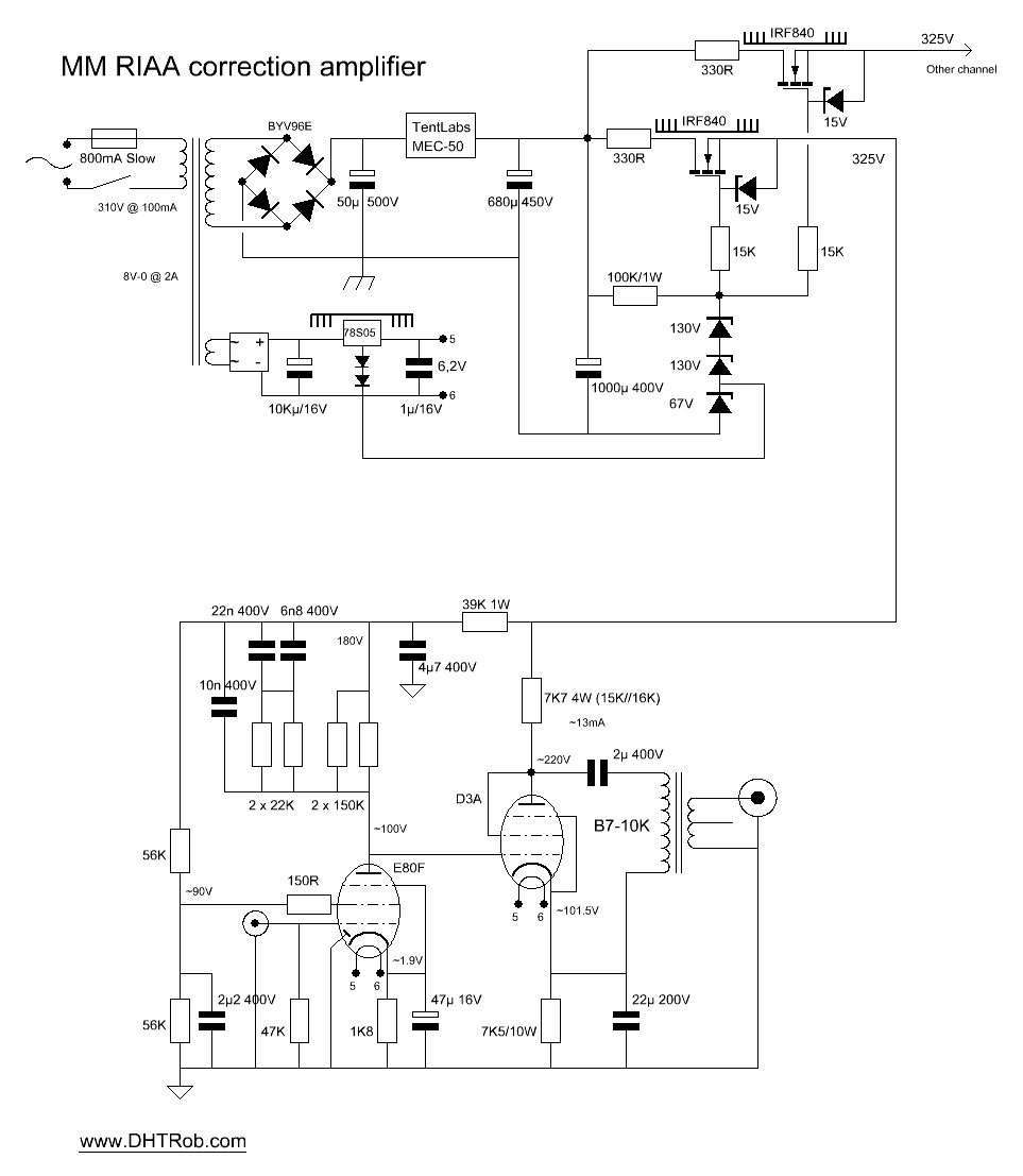
(Click on the diagram for my final preference wrt component values and brands..)
Input is a penthode, an E80F which is essentially an improved version of the EF86. RIAA-correction is incorporated in the plate load so most of the
gain must be supplied by this first stage. RIAA components are Orangedrop film capacitors and Kiwame resistors. The first stage is dc-coupled to the second
stage, a triode connected D3A. This D3A is loaded by a resistor and using a step-down parafeed output transformer. So basically it is a full pentode,
indirectly heated design. Power supply is dual FET-stabilised, one FET for each channel. It is high voltage, about 420 Volts DC raw and 325
Volts stabilised, needed because of dc-coupling and 2nd stage resistor loading. So please be very careful building this one as the IRF840's will supply plenty
of milliamps whenever they can.. Gain is sufficient for a MM cartridge to get to line level, for MC cartridges a pre-pre is needed. As can be seen in
the pictures, this design allows for an integrated compact build when a toroid power transformer is used. This is best placed on top of the chassis since
the used tubes are not that sensitive to strayfields. The FET-stabilised power supply takes a while to start up, almost 2 minutes to reach 320 Volts.
This is intended as the built-in delay allowing the tubes to warm up. The D3A cathodes are operated at approximately 100 Volts so the heatersupply is
lifted by 67 Volts using the diode array in the power supply. Using the Tentlabs mini electronic choke MEC50 in the first pi-filter allows for
for leaving out capacitance (electolytics) in the stabilised high voltage. Almost all remaining capacitors in the signal section are film types, including
the D3A cathode decoupling capacitors (I managed to squeeze these big Auricaps in as well). The E80F cathode decoupling capacitors are the only
electrolytics used in the signal section. These are Elna Silmics which are soundwise very much okay. The groundplane technique allows for very flexible
component placement, so very convenient. This groundplane serves as the zero or ground and is a copper plated pcb which makes it possible to directly
soldering components on it.
Performance is very much okay. It sounds detailed, fast and organic. Stage is deep and wide, pin-pointing performers and instruments is excellent.
Voices have weight (or throat) and are being reproduced realistic in size and energy. Things can be sauteéd by changing the coupling capactior,
of course. I use a 2μF paper-in-oil Kemet at the moment which is relative small in size. Using an audiophile capacitor will obviously change the sound but
be much bigger in size as well in price..
The pictures..
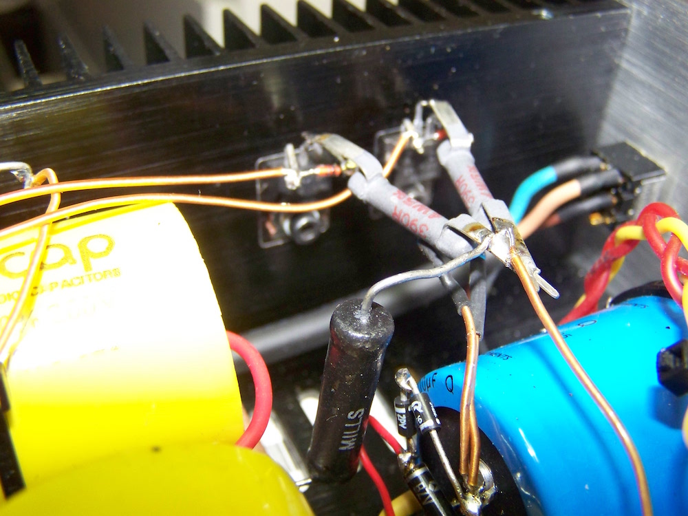
Dual IRF840, one for each channel.
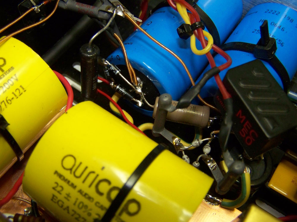
Lifting heater voltage from diode array.
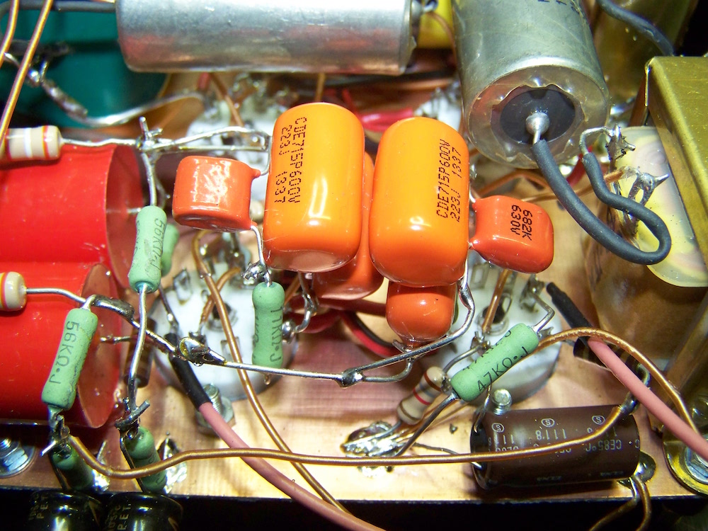
RIAA-correction with Kiwame and Orangedrop.
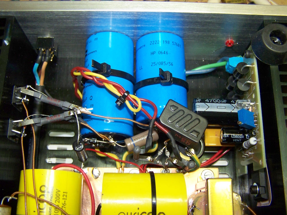
Power supply with Tentlabs MEC50 and heater supply.
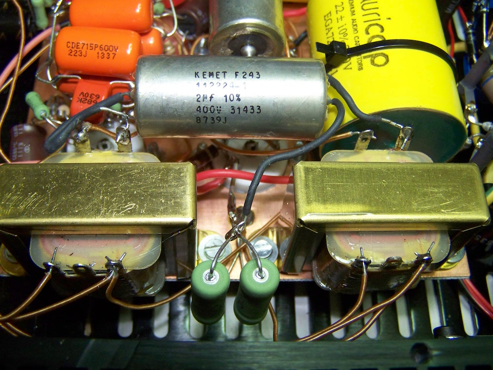
Magnequest B7 parafeed line-out transformers and Kemet paper-in-oil capacitors. D3A cathode resistors situated for optimal cooling.
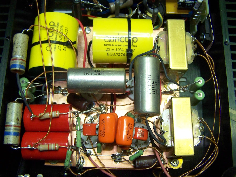
Signal section with the huge Auricap capacitors for cathode decoupling D3A. On the left the plate resistor for the D3A placed against the heatsink.
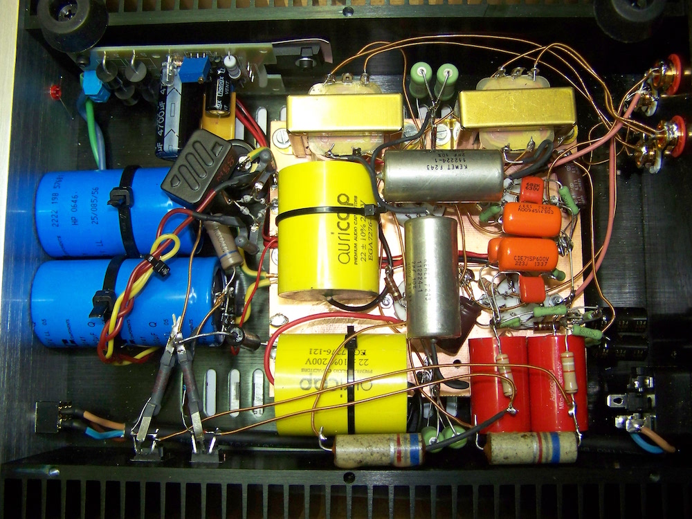
Overview, click it to enlarge..
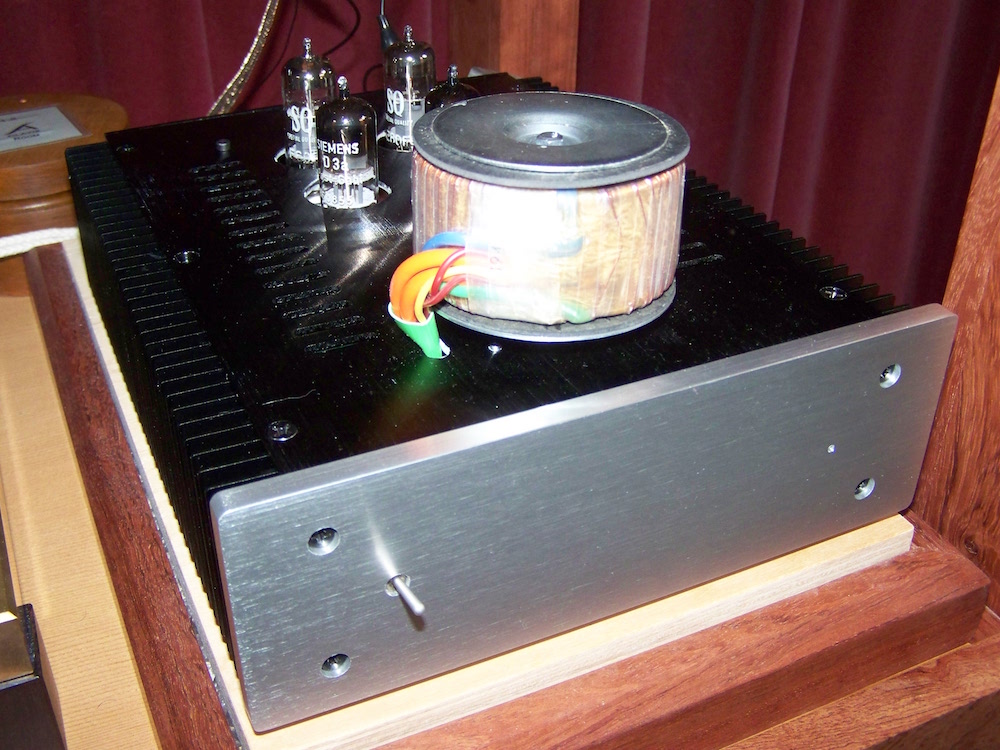
The chassis (China made) with on top the power transformer still needing a cover..
Well this concludes another phono-amplifier. I am enjoying it!
The former story, my quest so to say, can be found on page 2..
