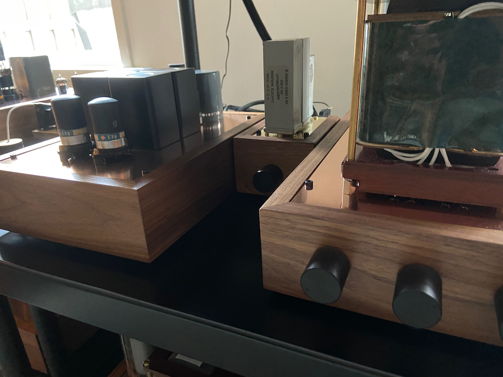
A MC-pre-pre by Audiomagic
Introduction.
Two years ago, in France during ETF, I consulted Peter from
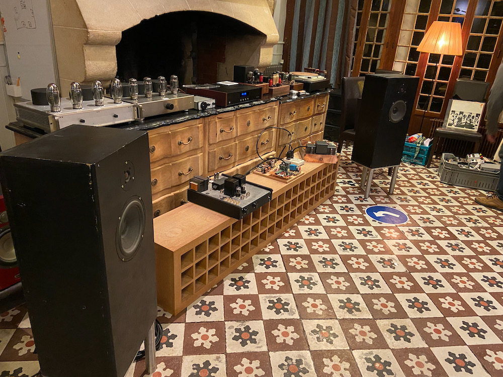
The set-up at ETF-21 with VanderVeen, Tentlabs, DHTRob and Audiomagic.
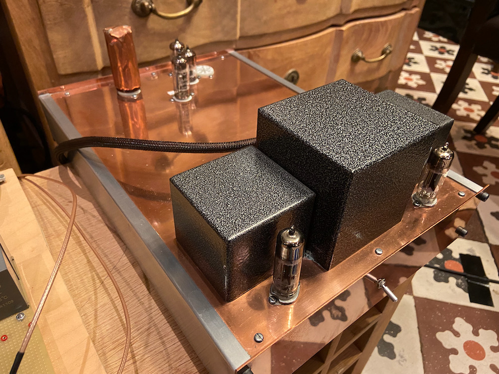
The marvellous MC-MM Phono preamplifier by Audiomagic.
The design.
Explanation given at the site: "A stage with selected, very quiet, FETs in common-source
configuration with 30dB of amplification." Power supply is very quiet as well, around
1µV and has a PSRR of 110dB. The whole is built on one PCB which makes for a very compact
design which can easily be fitted into existing phono-amplifier designs as well. It runs at
around 18 Volts DC at 80mA of current. So a very small toroidal transformer with a simple
C-R-C psu can complete the PCB. Standard the MC-pre-pre is fitted with LeClanché
coupling capacitors. Of course these can be replaced by more exotic ones, if needed. It
has an input impedance of 47K, yes, 47K. Peter is convinced that most cartridges benefit
from this. This can be altered as well upon request. N-eq. input noise of the fet is around
100 nV, which RIAA-weighted comes down to a SNR of 79 dB ref 0.5 mV. How about that?
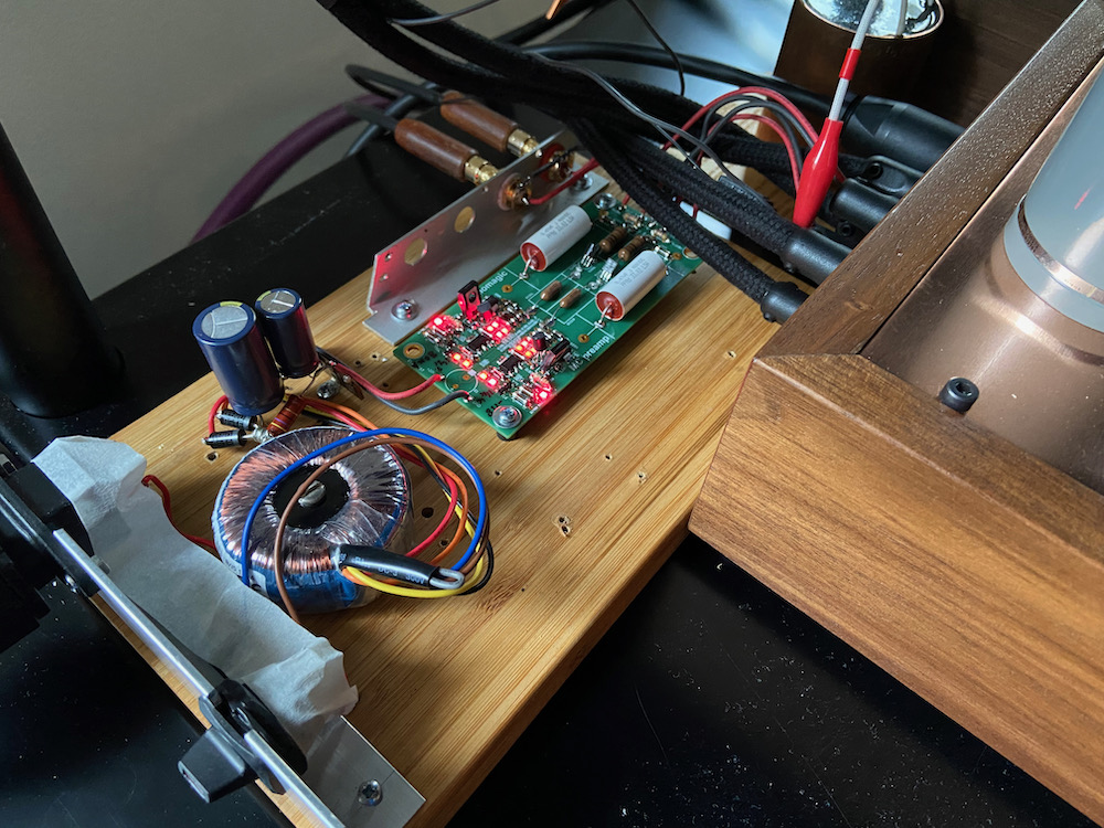
The standard PCB with PSU built onto a test rig.
The sound.
The test rig was placed just behind the phono amplifier and connected to the MM-input which
has a 100K impedance. Despite the open design it was very quiet! Right form the first
notes it became clear that this is indeed a VERY good MC-pre-pre device. The two cartridges
used are the Dava Reference as well as the Koetsu Tiger Eye Platinum. Later the
hot rodded Supex SD-909 was used with great result as well.
What really stands out is, besides being VERY quiet, is that the lows seem to have extra punch. Not
like a loudness effect, but qualitative better. Wow!
Peter advised me to change the coupling capacitor to an oil-type to get more fluid sound,
and so I entered the next phase.
Coupling capacitors.
Do these have an effect on sound? Many people are convinced that this is not the case,
this is supposedly an audiophile deviation being exploited by many vendors. In this case the
coupling cap needs to clear around 8 Volts DC from the signal before being fed into the phono
amplifier. So low voltage compared to most coupling capacitors used in tube amplifiers. As the
PCB allows for small and bigger capacitor I tested most that I had on hand. I can tell that
changes in sound are very much audible and I don't care if this is subliminal. It is just fun
and allows for tuning sound to preference. Below some photos of different types of capacitors
being auditioned for longer periods than just 10 minutes. Alle of these have there merits and
qualities, again this is subjective. Low voltage as well as high volage have been in there, and
I know that there are endless possibilities. But when the goosebump factor was reached, I
decided to stop.
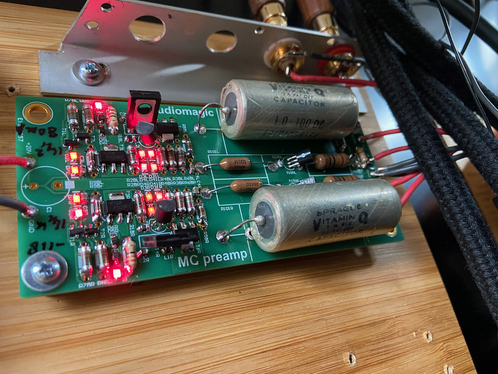
Vitamin-Q, 1µF 100v DC, a real romanticus.. If you like the "old radio sound"
this might be your sound.
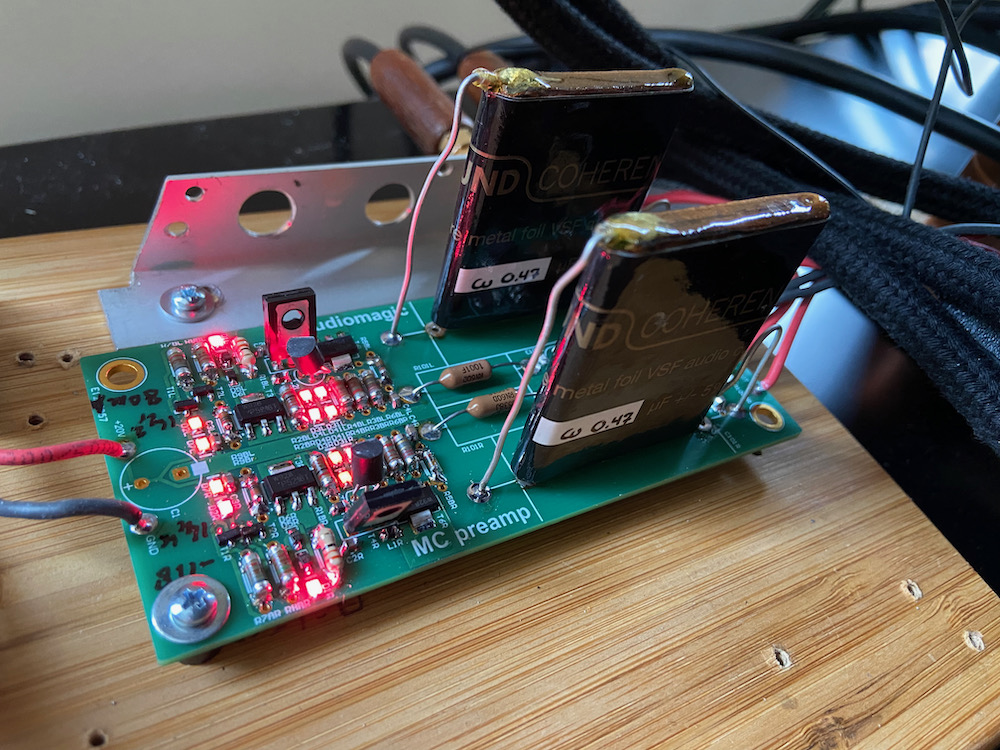
Duelund VSF, 0.47µF 100V DC, a bit shallow sound.. Hard to explain, but no good tone, excellent
dynamics however.
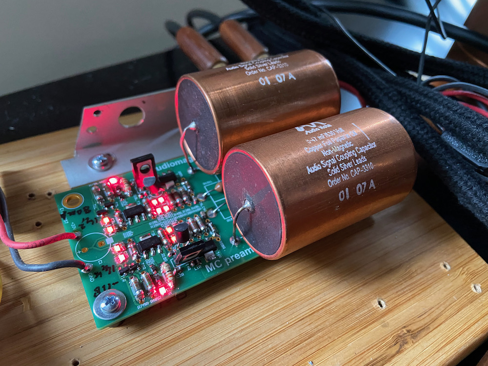
AudioNote copperfoil, 0.47µF 630V DC, a dull performer.. Probably because of the higher
voltage rating, so thicker insulation makes for dull sound?
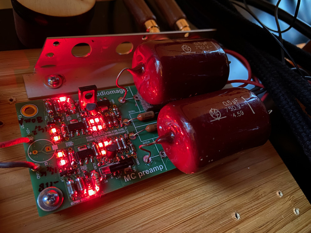
Vintage paper capacitor, 0.5µF 750V DC, very natural sound.. A bit like the musicality of
the Vitamin-Q but a bit more modern. Beware as these types will leak DC at higher voltages because
of their age.
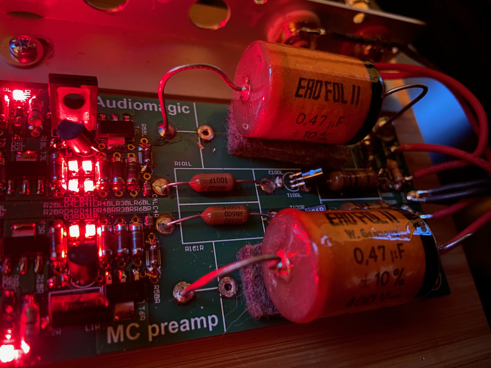
Erofol II, 0.47µF 400V DC, a bit plastic sounding.. A bit harsh highs, or better, unnatural
highs.
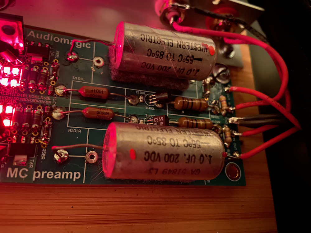
Western Electric 1µF 200V DC, a bit less romantic than Vitamin-Q.. Can be its cousin though,
be it the more happy cousin.
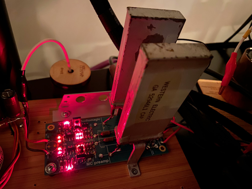
Western Electric 52946L1, 0.5µF 300V DC, goosbump factor from knees up to ears!
So when reached the goosbump factor, the experimenting stopped and it was time to build
it into a chassis.. Or?
The power supply.
As the regulated supply on the PCB adds for 110dB noise reduction, would changing the SPU
have any audible effect? Peter replied with a simple line: "That would not surprise
me at all". I still had a tubed power supply for the Dava's field coil at hand. This is built
using a center-tapped 42 Volts transformer which supplies both the heater and the plates of the
PY500A's. As the voltage drop of a PY500A at 80mA is around 10 Volt, this results in a 19 Volt
PSU which allows for a C-L-C PSU to end up with a little less then 18 Volts DC. A change was
made in the test rig allowing switching back and forth from the original PSU to the tubed PSU.
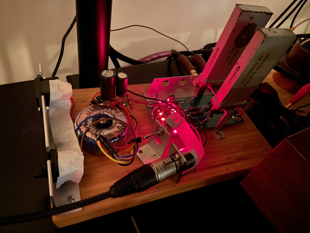
Note the switch and extra XLR-connector which leads to the tubed PSU.
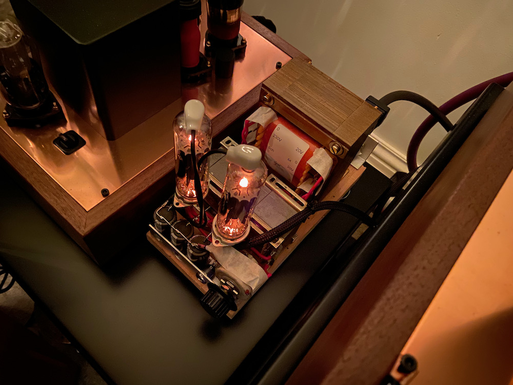
The somewhat oversized tubed PSU using PY500A rectifiers.
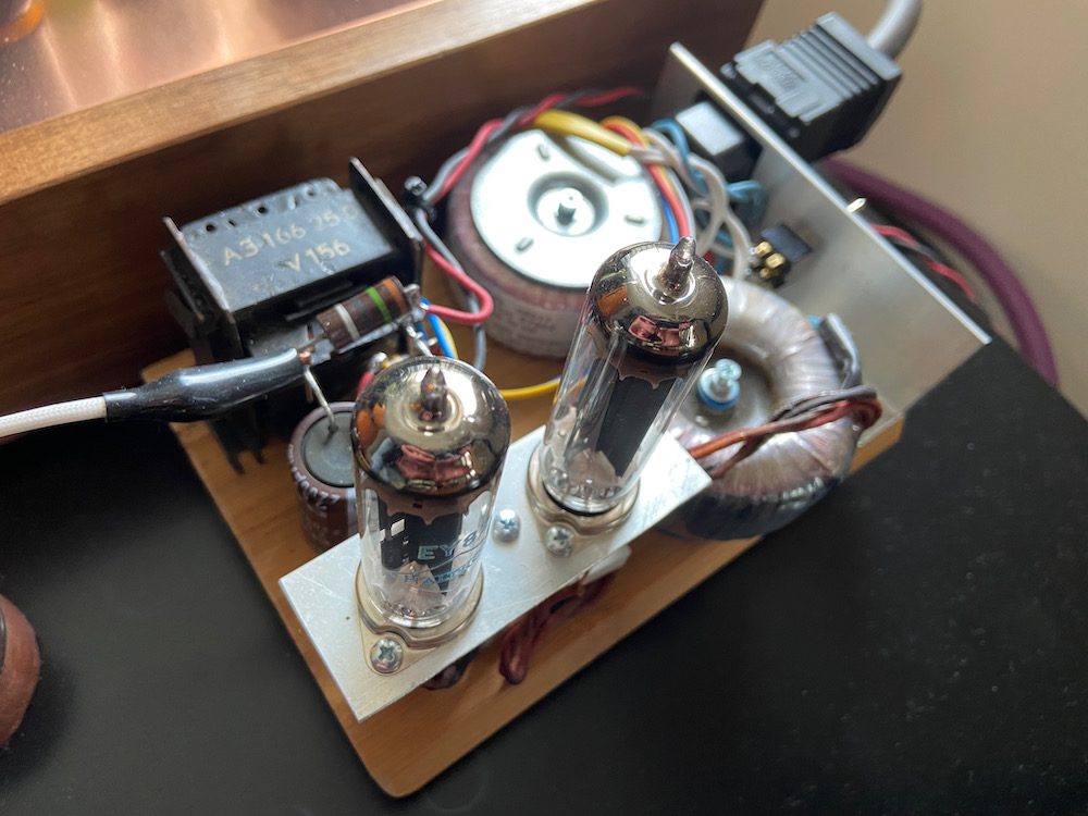
And the bespoke PSU using PY82 rectifiers, still waiting for a chassis..
With different friends we changed from SS to tube and back again, all in favor of the tubed
supply. Better flow was noticed with tubes where SS had tighter bass. In here as well a
preference but in this case all had a preference for flow against tighter bass.
Are we done yet?
Last capacitor standing..
As the PSU will be placed in a separate chassis, it is good to have a smaller value capacitor
at the input of the umbilical cord. In this case I chose a Western Electric as well, a 4µF
200V DC per channel. Again this proved to be audible in a positive way. I did not experiment
with other types of capacitors since I noticed that the goosebump factor remained.
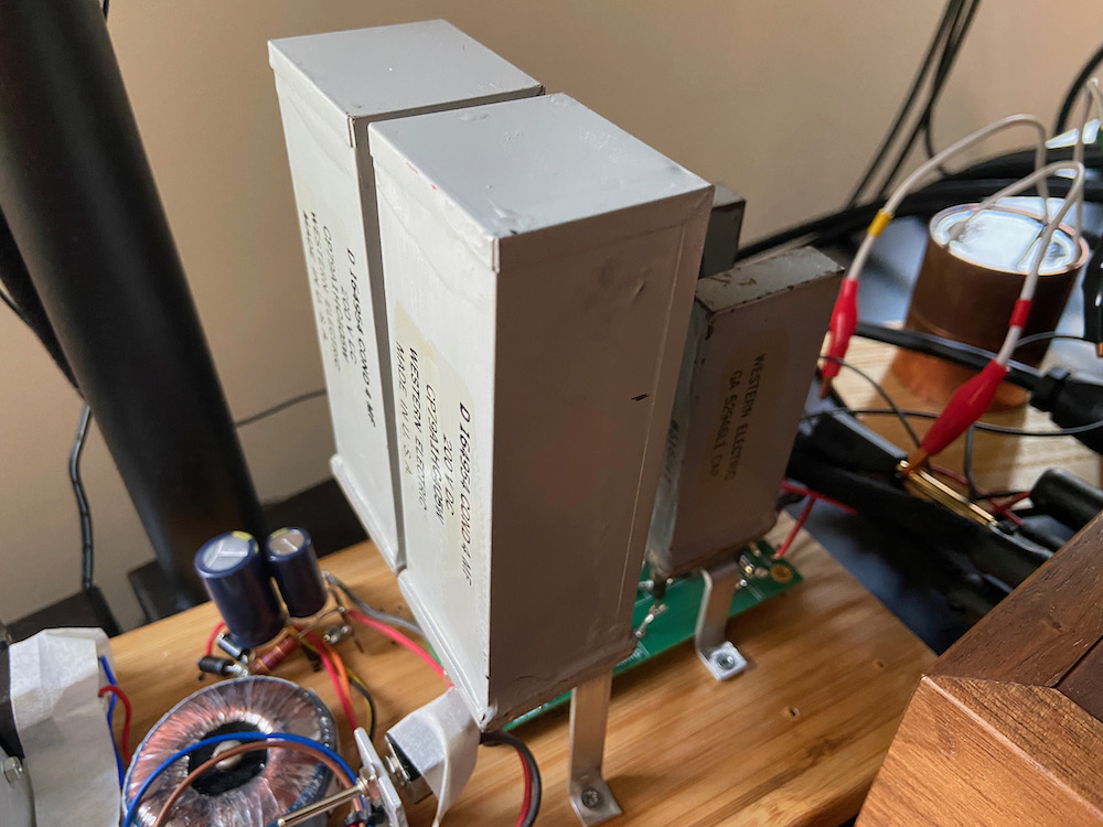
Four huge Western electric capacitor serve the tiny PCB..
The final build.
End of experimenting, time to built it into a chassis. As I use many phono amplifiers, it will
have its own chassis with a separate PSU. And it will be small sized so it can stand between phono-
and pre-amplifier. Two source inputs and one shorted input connected to a shorting Elma switch.
As it will be small, the PCB will be stacked between the faceplate and the source select
switch which has its own mounting plate. It looks a bit odd with the four WE-caps on top but
plays very convincingly! Below a photo of the MC-pre-pre placed between the LCR-phono
amplifier and the huge RS282 preamplifier and below a gallery which shows the building process.
