A preamplifier with Monolith and the RS55
Introduction.
What about a preamplifier with tubes that are not intended for this use? Why would we NOT do that?
Looking at the web not many have gone this road, or have published about it. The latter might be the case, people must have built stuff
but not shared the information, be it succesfull or unsuccessful. I know by experience that talking about successes is easier than
talking about failures, although those lessons are very valuable. So.. is this a write up about a failure? Not exactly as failures
can be turned into successes, maybe with a little help. As well with this project. It started out what felt like a marvellous idea
but I failed to successfully realise it. Then an unexpected helping hand came realising that marvellous idea after all.
The hefty transmitting triode..
Hefty? Yes, most of these are designed for power, transmitting power. So that means high frequency, much higher than the audio range.
To be able to deliver power, energy is needed. That energy is to be delivered by the cathode: an electron swarm that is caught by the
anode and can be influenced by the grid. We need power for both cathode and anode. So logic dictates that if we need transmitting power,
power on those electrodes need to be increased as well. As you know power is derived from the product of voltage and current. Most of
the transmitting triodes run on high voltage and lower current for the anode and high current and lower voltage for the cathode. Both
are challenging in preamplifier design and most certainly not needed for their function.
But they look gorgeous! Tall and bright!
So when my friend came along with a pair of RS55 and I read the datasheet, I had to build a preamplifier using them..
The RS55.
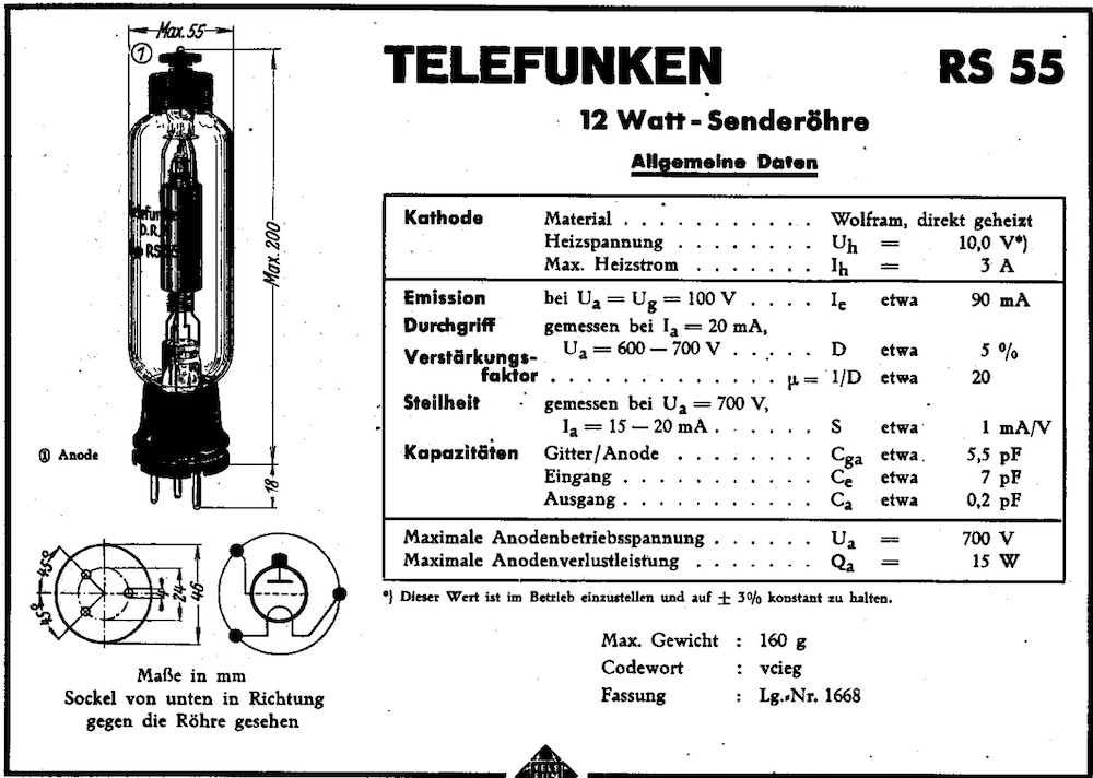
Looking at the datasheet we can read that power needed for the cathode is around 30 Watts. That is a lot but earlier experiments
with the 845 proofed that that is doable with the use of Coleman regulators .
The power needed for the anode is at max transmitting power around 30 Watts, where the maximum power dissipated by the anode itself
is 15 Watts. That is doable as well. As this is one of the first transmitting triodes, it is fairly inefficient and not designed for
high output power. Interesting! Even more interesting is that it can be run with zero bias at a lower plate voltage and maximum grid
current is only 4mA. Even more interesting!
I also noticed that the cathode is made out of wolfram which is the same as tungsten. Also the datasheet showed that it could be loaded
with a relative low impedance transformer!
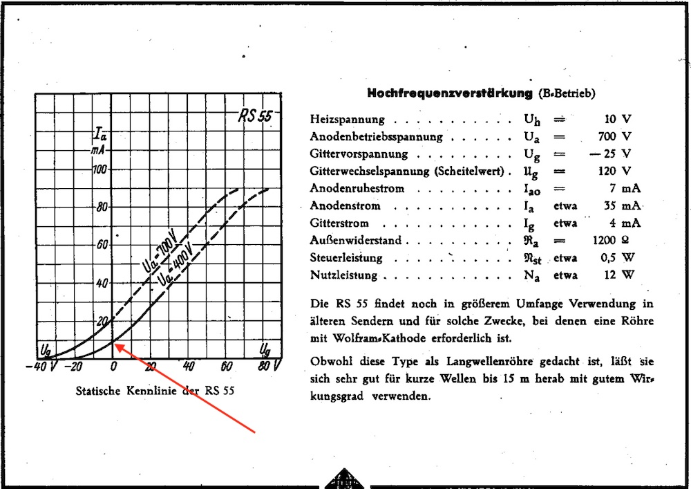
The aimed for RS55 operating point.
As this is a triode for transmitting purposes, these are designed for grounded grid operation. So when it is swung into more power,
grid current will be no issue. As I did not want to use a capacitor to couple the signal into the cathode, the question to be answered
was when the grid starts to draw current, at what signal level. My assumption was that at line level this might not yet occur which
opens the possibility for using an input transformer without saturating the core as a result of grid current. So could I be looking at
a preamplifier without a cathode resistor and decoupling capacitor?
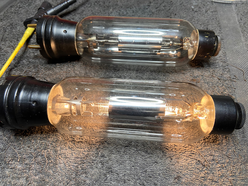
Telefunken RS55 with wolfram cathode!
The design.
After making sure that grid current draw is not present at line level, the design could be finalised. Power supply should be able to deliver
power for both the cathodes and anodes. So two times 10Volts at 3Amps for the cathodes and 400Volts at 20mA for the anodes. Power supply
and amplifier will be in separate boxes connected with an umbilical cord carrying only DC. As I like to multipurpose chassis, the power
supply originally built for the 845 preamp and RV218 preamp, could be )re(used. Amplifier circuit is pretty straight forward
consisting of input transformer, RS55, line output transformer and autoformer for attenuation. The built is according to my earlier posted
article about "Preamplifier design using power triodes".
Chassis is made out of American walnut supporting a 2mm thick copper faceplate. Three selectable inputs complete the design. All that is
left to decide which component brands to use. Already in stock were the input transformer and autoformer, a Tamura TD-1 1:1 line-in
transformer and dual mono Tribute autoformers. The Tribute autoformer can handle up to 8V RMS signal at 50hz which is more than sufficient
for preamplifier use. Looking around the web I stumbled upon Monolith Magnetics. Not new
to me but never used by me. So I contacted them and ordere a pair of Summit line output transformers, the SL-01/40. Specs were compatible
to the RS55 datasheet and they look stellar. Within two weeks these arrived and I could start building. Pictures of the building process
are at the bottom of this page.
The result..
The built itself was a weekends work. When all components are at hand, a layout is quickly made and chassis can be prepared for drilling and
cutting the necessary holes. As said, it is a minimalistic design, so apart from the Coleman heaters we are talking about two power supply
capacitors and resistors, two input- and output transformers, two attenuators and a bunch of wire. No more.
When finished all ramped up as expected and first measurements were made. This very old wolfram cathode emits a very white light, even brighter than
for instance the Chinese 845 versions, way cool!
And that is where the fun stopped. Or disappointment came along.
A design mistake..
The preamplifier measured far from full bandwidth. High frequency response was more than okay but low frequency response nearly touched 70Hz.
Ouch! That is not good. Just to get a taste of the sound I hooked the preamp in my set and was amazed by the sheer transparency and clearness
in tone and details. Very fast sound. But.. no bass. Maybe that is the cause of the transparency?
Measurements showed that all was full bandwith apart from the Monolith line-out transformers. So I contacted them again by an email explaining
the situation, accompanied by the diagram and asked for assistance. A reaction followed quickly and a telephone conversation followed with Yves
of Monolith Magnetics.
My design mistake..
During the conversation Yves explained that he was intrigued about the diagram and choice in tube, a high Rp one. He had no knowledge about the RS55 so had
it looked up and came quickly to the conclusion that the Summit line-out transformer was not suitable for the job. Reason was quite simple, the
RS55 internal resistance was too high! I had been mistaken by adopting the recommended load (Aussenwiderstand) of 1200Ohms for audible frequencies where
it is only suitable for high frequency applications. Actually the internal resistance is the determining factor for the load, and in this case at
a figure of 20KOhms the Summits inductance was way to low. What a rookie mistake by me.. Rookie mistake? Yes, I should have done the math with
amplification factor times transconductance, 20 x 1 equals 20K internal resistance..
However Yves offered to me to try to make the Summit suitable for the RS55 by decreasing the airgap in the core of the Summit. That will increase
inductance allowing for better low end response. What about that, an unexpected helping hand!
Looking at the datasheets the SLX-01/10 has more than twice the inductance compared to the SL-01/40. If only I paid better attention..
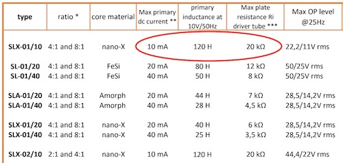
After a couple of weeks Yves contacted me and told me that it was not possible to create enough inductance for the RS55 with the SiFe core. He had to
switch to a Nano-X core and then could get as low as 30Hz. Way to go! But days after that he contacted me again and said that 30Hz was not good enough,
so he had made a new design that went all the way down to 8Hz in the test set-up. Amazing! Two weeks later the new line-out transformers were delivered and
could replace the Summits. ..so in the end maybe I should be very happy that I made the rookie mistake?
The end result.
Swapping the transformers was easy and increased the bandwidth down to 10Hz at -1dB. Upper limit is just below 70Khz. More than sufficient!
Putting the preamp back in the system proved that the extreme transparency was still there only now accompanied by sufficient bass. The Monoliths
took a while to run in but surprised me from the start. Their sound is remarkable detailed with lots of tone, the right (real) tone that is. Imaging
is spacious, left to right, front to rear. Combined with the Tamura's and Tributes it is the most pleasing preamplifier I have build (so far). It has
very little components and is pleasing for the eye as well. Of course transformers do have a price, most of the time that price relates to quality,
as it is in this preamplifier, it will set you back quite some money. But to my opinion it is worth the money. Comparing it to some commercial designs
in the upper echelon proved this to be true. Sound-quality-wise that is, aesthetics is a different topic as it remains subjective. And.. compared to
those prices this preamp is a steal..
A word on safety as well!!
The RS55 has a top cap carrying 400Volts. It looks very nice and is easy operated but meant to be built in an enclosure, ensuring that voltage
untouchable. The way I built it is very dangerous during operation.. To deal with that I have ordered some neoprene covers that can be put over
the topcaps and can withstand the high temperature. On the photos these are not yet implemented.. Please be carefull!
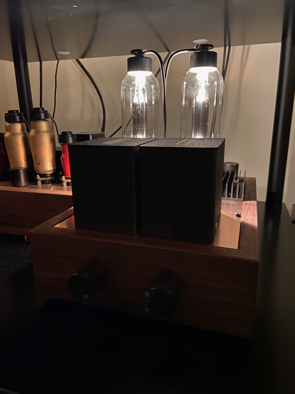
The finished preamplifier, stunning sound, stunning looks!
Below a gallery with pictures of the building process.. The diagram can be accessed here.